ELECTRONICS FOR BEGGINERS
Dr. Saurav Chakraborty
An electrical current
is the flow of electrons in a wire. Electrons flow in a “closed loop”. Loop is
formed by a path if the negative and the positive terminal of a battery is connected.
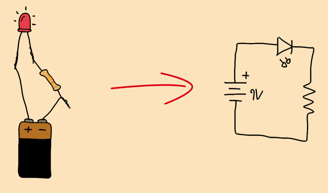
For example if you
connect a small light bulb to the positive and the negative side of a battery,
you will get a closed loop where electrons can flow and make the lamp glow.


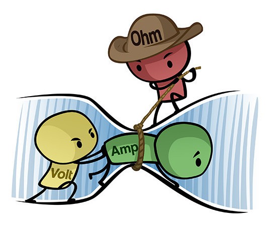
Basic Understanding of Voltage, Current and
Resistance. Current flows,
resistance resists, voltage pushes.
And they all affect each other.
To understand how they
work in a circuit following steps to be followed. You should also know how
these components work and what they do in a circuit.
Resistance is an
element which opposes the flow of current
Resistance is a current limiting device when current of any circuits
needs to be reduced then this is used.
Now you can made circuit. You can see now how circuit diagram works. Resistors can be made to control the flow of
current, to dissipate power. Basic unit is
ohms, (Ω)
ELECTRONIC COMPONENTS
:
Components can be
classified into
1. Passive Components: Components like
resistance, capacitance inductance.
2. Active Components: Semiconductor
Devices such as
diode, zener diode, and varactor diode
etc. Uni-junction transistor, Bipolar Junction Transistor (BJT), FET, silicon, rectifier
etc., Light emitting diode, photosensitive transistor etc.are active
components.
RESISTANCE
To know value of Resistance, they have
different colored rings around their body (see Figure). The first ring represents
the first digit of the resistor’s value. The second ring represents the second
digit of the resistor’s value. The third ring tells you the power of ten to
multiply by. The final and fourth ring represents the tolerance.
Color value:-Black 0, Brown 1, Red
2, Orange 3, yellow 4, Green 5, Blue 6, Violet, Gray 8 and White 9.
COLOR
VALUE
series circuit
A series
circuit is a circuit in which resistors are arranged in a chain, so the
current flows in one path. The current is the same through each resistor. The
total resistance of the circuit is found by adding up the resistance values of all
resistors:
Equivalent
resistance of resistors in series: R = R1 + R2 +
R3
If battery voltage is 10 V, according to Ohm’s Law, V = I R the total current in the circuit is: I = V / R = 10 / 20 = 0.5 A. The current through each resistor would be 0.5 A.
Parallel circuits
A parallel circuit is a circuit
in which the resistors are arranged with their heads connected together, and
their tails connected together. The current in a parallel circuit breaks up,
with some flowing along each parallel resistance and re-combining when the
branches meet again. The voltage across each resistor in parallel is the same.
The total resistance of a set of
resistors in parallel is found by adding up the reciprocals of the resistance
values, and then taking the reciprocal of the total resistance: equivalent
resistance of resistors in parallel: 1 / R = 1 / R1 + 1 / R2 + 1 / R3 +...
Voltage drop V = I.R, I is current,
Power
dissipation P = I2R = V2/R
A parallel circuit is shown in the diagram above. In this case the current supplied by the battery splits up, and the amount going through each resistor depends on the resistance. If the values of the three resistors are:
The individual currents can also be found using I = V / R. The voltage across each resistor is 10 V, so:
I1 = 10 / 8 = 1.25 A
I2 = 10 / 8 = 1.25 A
I3=10 / 4 = 2.5 A
Note that the currents add together total become 5A.
A parallel resistor short-cut
You have three resistors
in parallel, with values 6 ohms, 9 ohms, and 18 ohms. The smallest resistance
is 6 ohms, so the equivalent resistance must be between 2 ohms and 6 ohms (2 =
6 /3, where 3 is the number of resistors).
Doing the calculation
gives 1/6 + 1/12 + 1/18 = 6/18. Making this upside down gives 18/6 = 3 ohms,
which is certainly between 2 and 6.
Remember that for
resistors in series, the current is the same for each resistor, and for
resistors in parallel, the voltage is the same for each one.
Circuits with
series and parallel components
More examples
of resistance calculations
In the
following circuit calculate the total current
taken from the 12v supply.
At
first glance this may seem a difficult, but if we look a little closer we can
see that the two resistors, R2 and R3 are connected together in
a “SERIES” combination so we can add them together to get an equivalent
resistance. Resistance for this combination would therefore be:
R2 + R3 = 8Ω + 4
Ω = 12 Ω
So we
can replace both resistors R2 and R3 above with a single
resistor of resistance value 12 Ω
So our
circuit now has a single resistor RA in
“PARALLEL” with the resistor R4. Using our resistors in
parallel equation we can reduce this parallel combination to a single
equivalent resistor value of R(combination) using the formula for two parallel
resistors as follows.
The
resultant resistive circuit now looks something like this:
We can
see that the two remaining resistances, R1 and R(comb) are connected together in a “SERIES”
combination and again they can be added together (resistors in series) so that
the total circuit resistance between points A and B is given as:
R( A B ) = Rcomb + R1 = 6
Ω + 6 Ω = 12 Ω.
and a
single resistance of 12 Ω become
total of the four resistors connected together in the original circuit.
So any
complicated resistive circuit consisting of several resistors can be reduced to
a simple single circuit with only one equivalent resistor by replacing all the
resistors connected together in series or in parallel using the steps above.
when a LED is
connected to a
Capacitors
These are simple
components. It consists of two pieces of
conducting material
(such as metal) separated by a non-conducting (insulating) material called a
dielectric. The
capacitance units is farads, F, pF.
Value of the capacitance is given by
Its value and the max specify. V Voltage which
can be safely applied to its
When capacitor is put in parallel the
overall capacitance C is
C = C1 + C2 + C3 + ------
and in series—1/C=1/C1+1/C2+1/C3---
The diode as a switch
• Diodes can be used as passive
switches – to conduct positive voltages along one path and negative voltages
along another
• Example: voltage doubler
10V
There are
two types of main capacitor-Ceramic capacitor and Electrolytic capacitor. There
are also other types of capacitors.
They are often used to make rectified DC
supply ripple free. In a radio tuning into the station is done by a capacitor. Capacitor can be considered as a
battery with very low capacity. It can be charged and discharged just like a battery.
The capacitor is often
used to introduce a time-delay in a circuit, for example to blink a light. It’s commonly used for removing noise and makes DC voltage of
a circuit stable. Using
Capacitors For Filters
You can also
combine capacitors and resistors to form filters to remove specific
frequencies. In an audio system you can remove the high frequencies. This is
called a low-pass filter.
There are 2 types of capacitors ceramic and
electrolytic. There are also other types of capacitors.
INDUCTORS:- Like capacitors,
inductors also store energy in one part of AC cycle and return it during the
next part of the cycle.
Inductance is that property of a
device that prevents change in current through the device. Inductors are
components designed for use in circuits to resist changes in current and thus
serve important control functions. Because inductors tend to reject the flow of
rapidly changing currents, they can be used to filter out high frequency signals.
TRANSFORMERS:
The transformers used in electronic
circuits may be classified into three classes depending on their application.
Power transformers used for power
supply. Audio transformers are used as input and output transformers and
isolation transformers.
Pulse
transformers used in many types of pulse circuits.
Transformer with magnetic core
It has two windings; 1. primary and 2.
secondary
If ac voltage is applied in primary
winding, magnetic field is produced which cuts the secondary winding of the
transformer and voltage is induced in it? It can be step up transformer and
step down transformer.
• This is called a transformer.
• For AC (time-varying) signals, it
transforms the voltage applied in primary is transformed in secondary according
to its turns ratio.
• A transformer isolates the
two sides of the transformer – there is no electrical connection between two
windings
other than through
the magnetic field. This is desirable for safety reasons
If VA
is the primary input voltage and VB is the secondary voltage output
and number of turns of primary is N1 and
number of turns secondary is N2, voltage ratio of transformer will be
VA/VB = N1/N2, VB =
VAXN2/N1 and IB = IAX Ni/N2. IA and IB
are the primary and secondary current.
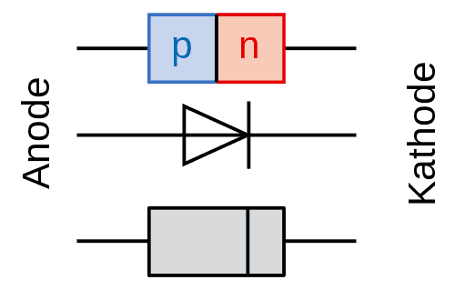
DIODE
Now you can try to understand some components. Two types of semiconductor material are there which known
as P - type and N – types of semiconductors such as silicon and germanium.
p-type : Impurity Of lower group, it
contain excess of holes or deficiency of electrons.
n-type : impurity of higher group,
contains excess of electrons or deficiency of holes.
What is a Diode?
Diode is a semiconductor device with two
terminals, allowing the flow of current in one direction only and blocks current flowing in the other direction.
•When the anode and cathode of a pn-junction
diode are connected to external voltage such that the potential at anode is
higher than the potential at cathode, the diode is said to be forward biased.
–In a forward-biased diode current is
allowed to flow through the device.
•When potential at anode is smaller
than the potential at cathode, the diode is said to be reverse biased. In a
reverse-biased diode current is blocked
The
diode symbol is like this:
A Diode can be connected as bellow
In the circuit above the diode is connected
in the right direction. So, current can flow through it to glow the LED. But if
the diode is connected in the opposite direction current will not flow and so
LED will not glow
A lot of the devices, we use, need direct current (DC). To get
DC from AC we need a rectifier circuit. It rectifies alternating current (AC)
power supply in our home to get direct current (DC). It is used as rectifier
and converts AC
input voltage to a pulsed DC output voltage to DC power supply. Fig below is a
half-wave rectifier.
Diode Applications
—Half Wave Rectifier
Diode converts ac input voltage to a
pulsed dc output voltage.
Whenever the ac input becomes negative
at diode’s anode, the diode blocks current flow. Output voltage become zero.
Diode introduces a 0.6V drop so output
peak is 0.6V smaller than the input peak voltage.
The output frequency is same as the
input frequency.
Vin
Full wave
rectifier
Full Wave
Rectifier
• A full-wave rectifier does not block
negative swings in the input voltage; rather it transforms them into positive
swings at the output.
• To understand its working, follow
current flow through pairs of diodes in the bridge circuit.
• It is easily seen that one pair
(D3-Rout-D2) allows current flow during the positive half cycle of Vin while
the other pair (D4-Rout-D1) allows current flow during the negative half cycle of Vin.
Output voltage peak is 1.2V
below the input voltage peak.
The output frequency is twice the
input frequency.D1 D3 D2
A
full-wave rectifier does not block negative swings in the input voltage; rather
it transforms them into positive swings at the output. The p-side is called
anode and the n-side is called cathode. To
gain an understanding of device operation, follow current flow through pairs of
diodes in the bridge circuit.
AC to DC Power Supply
from AC power Supply
An AC to DC power supply is built
using a transformer and a full-wave rectifier. Transformer is used to step down
the input voltage. Rectifier converts AC to pulsed DC. A filter capacitor is
used to remove pulses. Capacitor must be large enough to store sufficient
charge to provide a steady current supply to the load: It is used in mobile
charger, amplifier, Radio, TV and in almost all equipment we use and find all
around.
How a Diode Works
The diode is created from a PN junction. You get a PN
junction by taking negative doped and positive doped semiconductor material and
putting it together.
Types of Diodes
There are many types of diodes.
The most common are signal diodes, rectifier diodes, zener diodes and Light-Emitting
Diodes (LED). Signal and rectifier diodes are almost
the same thing except that rectifier diodes are built to handle more power.
Zener diodes are
diodes that make use of the breakdown voltage when applying voltage the “wrong”
way. They act as voltage regulator.
You have to apply
voltage in the “right” direction – from positive to negative – for the diode to
start conducting. Usually this voltage is around 0.7V.
If you apply a enough voltage in the “wrong”
direction, the diode will break down and current will pass in this direction
also.
ZENER DIODE:
These diodes are operated in reverse
bias mode, as the reverse bias is increased the resistance remains constant
until a certain value known as avalanche point is reached due to avalanche
effect the current suddenly increases and the voltage across it becomes almost
constant.
Characteristic
of Zener Diode
Zener voltage may vary from as little as 3
volt to 150 volts depending on the way the Zener is manufactured. It is used as
the voltage regulator.
TRANSISTOR
TRANSISTOR: - is also
a semiconductor device used for amplification and sometimes rectification.
There are two types of Transistor: - NPN and PNP.
In NPN transistor a small input current and a
positive voltage applied in its base (with VB>VE). This allows a large
current to flow from collector to emitter.– In PNP transistor a small output current
and a negative voltage is applied in its base (with VB<VE). It allows a much
larger current to flow from emitter to collector.
The
transistor may be taken as a switch controlled by an electrical signal.
If you put about 0.7 volts between the base and the emitter,
it turns the transistor on.
Note that this is true for NPN transistors and PNP
transistor.
But,
instead of two states (ON or OFF), it can also turn on by controlling the base
current.
A bit
of current on the base produces a current about100 times more (depending on the
transistor) through the Collector and Emitter. We can use this effect to build amplifiers.
Let’s look at an example
In circuit above you can see how
transistors work. A 9V battery connects to an LED and a resistor. But it connects through the
transistor. This means that no current will flow though LED circuit until the
transistor turns ON.
To turn the transistor ON you
need to apply 0.7V from base to emitter of the transistor. Imagine you have a
small 0.7V battery. (In a practical circuit you would use resistors to get the
correct voltage from voltage source).
When you apply the 0.7V battery from base to emitter, the
transistor turns ON. This allows current to flow from the collector to the
emitter. And the LED is turned on and glows.
Here
transistor acts as switch.
A Bipolar NPN Transistor Configuration
The most commonly
used transistor configuration is the NPN
Transistor.
The junctions of
the bipolar transistor can be biased in one of three different ways – Common
Base, Common Emitter and Common Collector.
Here bipolar transistors is used at the
“Common Emitter” configuration using the Bipolar
NPN Transistor with an example of the construction of a NPN
transistor along with the transistors current flow characteristics is given
above.
The construction and terminal voltages for a bipolar NPN
transistor are shown above. The voltage between the Base and Emitter ( VBE ), is positive at the Base and negative at the
Emitter because for an NPN transistor the Base terminal is always positive with
respect to the Emitter. Also the Collector supply voltage is positive with
respect to the Emitter ( VCE ). So for a
bipolar NPN transistor to conduct the Collector is always more positive with
respect to both the Base and the Emitter.
NPN Transistor
Connection
The voltage sources are connected to an NPN transistor as
shown. The Collector is connected to the supply voltage VCC
via the load resistor, RL which also acts to limit the
maximum current flowing through the device. The Base supply voltage VB is connected to the Base resistor RB, which again is used to limit the maximum Base
current.So in a NPN Transistor it is the movement of negative current carriers (electrons) through the Base region that constitutes transistor action, since these mobile electrons provide the link between the Collector and Emitter circuits. This link between the input and output circuits is the main feature of transistor action because the transistors amplifying properties come from the consequent control which the Base exerts upon the Collector to Emitter current.
PNP Transistor
A PNP Transistor Configuration
(Note: Arrow indicate the emitter and conventional
current flow, “in” for a PNP transistor.)
The PNP
Transistor is the exact opposite to the NPN Transistor device
we looked at in the previous tutorial.
Basically, in this type of transistor construction the
two diodes are reversed with respect to the NPN type giving a Positive-Negative-Positive
type of configuration, with the arrow which also defines the Emitter terminal
this time pointing inwards in the transistor symbol.
Also, all the polarities for a PNP transistor are
reversed which means that it “sinks” current into its Base as opposed to the
NPN transistor which “sources” current through its Base. The main difference
between the two types of transistors is that holes are the more important
carriers for PNP transistors, whereas electrons are the important carriers for
NPN transistors.
Then, PNP transistors use a small base current and a
negative base voltage to control a much larger emitter-collector current. In
other words for a PNP transistor, the Emitter is more positive with respect to
the Base and also with respect to the Collector.
The construction of a “PNP transistor” consists of two
P-type semiconductor materials either side of an N-type material as shown
below.
The voltage between the Base and Emitter ( VBE ), is now negative at the Base and positive at the Emitter because for a PNP transistor, the Base terminal is always biased negative with respect to the Emitter.
Also the Emitter supply voltage is positive with respect to the Collector ( VCE ). So for a PNP transistor to conduct the Emitter is always more positive with respect to both the Base and the Collector.
The voltage sources are connected to a PNP transistor are as shown. The Emitter is connected to the supply voltage VCC with the load resistor, RL which limits the maximum current flowing through the device connected to the Collector terminal. The Base voltage VB which is biased negative with respect to the Emitter and is connected to the Base resistor RB, which again is used to limit the maximum Base current.
To cause the Base current to flow in a PNP transistor the Base needs to be more negative than the Emitter (current must leave the base) by approx 0.7 volts for a silicon device or 0.3 volts for a germanium device with the formulas used to calculate the Base resistor, Base current or Collector current are the same as those used for an equivalent NPN transistor and is given as.
Usage in circuits
It is most
important components in computers. Transistors can switch on small electric
currents and off. A small base current can
increase “main current” which flows through collector to emitter. Thereby, the
transistor can amplify a signal. When transistors
work as amplifiers it can boost the volume of sounds in audio devices. The transistor is the most important single component in
electronics.
It can transform small
electric currents into much larger ones. Transistors that work as switches act
as the memories in computers, Transistors
make up logic gates which make up all digital electronics such as a microprocessor
in a computer, laptop, mobile etc. Build several different circuits
where the transistor acts as a switch. Like the LDR circuit.
After completing this step you should know how to control motors, buzzers or lights with
the transistor.
And you will learn how you can use the transistor to sense. temperature or light.
More on the
transistor
Not only it
has just two states (on or off), it can also remain anywhere in between “fully
on” and “fully off”. So you will find basic electronics in
every computer, mp3 player, radio, TV, mobile and many other appliances in your
home, car, or on your body.
Each circuit has a
job. Components are interconnected to perform a specific task. First
learn about each individual component and how it works then learn about how to
interconnect them to make useful end products.
Other Transistor
Types: BJT, JFET, and MOSFET
• Bipolar Junction Transistor
(BJT)- NPN and PNP
• Junction Field Effect Transistor
(JFET) – N-channel and P-channel
• Metal Oxide Semiconductor
FET (MOSFET)
– Depletion type (n- and
p-channel) and enhancement type (n- and p-channel) BJT JFET.
JFET
• Junction field effect transistors
like BJTs are three lead
semiconductor devices.
• JFETs are used as: – electrically controlled
switches, – current amplifiers, and – voltage-controlled resistors.
• Unlike BJTs, JFETs do not require a
bias current and are controlled by using only a voltage.
• JFETs are normally on when VG - VS =
0.
• When VG - VS = 0,
then JFETs become resistive to current flow
through the drain-source pair “JFETs
are depletion devices.” Two types of JFETs:
– n-channel and p-channel.
• In n-channel JFET, a –ve voltage
applied @ its gate (with VG < VS) reduces current flow from drain to source.
It operates with VD > VS.
• In p-channel JFET, a +ve voltage
applied @ its gate (with VG > VS) reduces current flow from source to drain.
It operates with VS > VD.
• JFETs have very high input impedance
and draw little or no input current – if there is any circuit/component connected
to the gate of a JFET, no current is drawn away from or sunk into his circuit.
Visible-Light LED
• Inexpensive and durable.
• Typical usage: as indicator lights.
• Common colors: green (~565nm),
yellow (~585nm), orange (~615nm), and red (~650nm).
• Maximum forward voltage: 1.8V.
• Typical operating currents: 1 to
3mA.
• Typical brightness levels: 1.0 to
3.0mcd/1mA to 3.0mcd /2mA.
• High-brightness LEDs exist.
– Used in
high-brightness flashers (e.g., bicycle flashers).
LED give visual effect such as to show that the
circuit has power. You see these components everywhere: In your laptop, on your
mobile phone, on your cameraThe voltage does
not change for small, medium, surface-mount, or large LEDs.
LEDs in series and parallel.
Different-colour LEDs can be connected in series. Add up the
total Characteristic Voltage for the 5 LEDs and see if it is less than 12v.
The 220R resistor will have to be reduced to 47R to make the LEDs Bright.
The 220R resistor will have to be reduced to 47R to make the LEDs Bright.
Connecting LEDs in parallel |
Different colour LEDs cannot be
connected in parallel. The voltage across a red LED is 1.7v.
This becomes the "Supply Voltage" for the green LED and it is too low. The green LED needs a supply of 2.1v to 2.3v. Only the red LED will
illuminate.
|
How To Make Your Own
Printed Circuit Boards
To make a printed circuit board you need to:
1.Design schematics
2.Draw the circuit board layout
3.Get the board made
Schematic Diagrams
To make any electronic circuit, you start with a schematic diagram. A schematic is a drawing of a circuit. It tells you which
components are needed and how to connect these components.
Designing schematics
And
it’s really useful to know the basic electronics formulas:
Ohm’s law describes the relationship between current, voltage and
resistance. This lets you calculate the correct resistor values you need for
different parts of your circuit. V= R x I
Thevenin’s theorem explains how you can
simplify complicated circuits to make it easier to do calculations.
Kirchhoff’s current law states that the sum of all currents
going in and out of a node is equal to 0. You’ll see resistors everywhere. As the name suggests, they
resist the current.
You use the resistor
to control the voltages and the currents in your circuit.
If you connect the battery directly to the LED, Much current will flow through the LED. So
the LED will become very hot and burn out after a short time.
But – if you put a resistor in series with
the LED, you can control how much current going through the LED. In this case
we call it a current limiting resistor.
Electronic
circuits
The key to an electronic device
is not just the components it contains, but the way they are arranged in
circuit.
Designing Circuit Boards
From the schematics shown above, you design the circuit board. You do this by drawing the wires from the schematics and
placeholders for the different components.
PCB
.
PCBs PCBs
Then you create your circuit
board. You aiso can purchase. When your
circuit board is created in PCB or breadboard, you solder your components on to the board.. Your electronic
circuit is complete. There
are many different methods for mounting printed circuit boards. The simplest
method is using machine screws and spacers.
An
example of a printed circuit board, or PCB, is
shown below.
This board has copper-side-up: the side where
all the soldering is done. Each hole is ringed with a small layer of copper for
bonding to the solder. All holes are independent of each other on the board,
but the holes on a solderless breadboard are connected together in groups of
five. ?
Printed circuit board (PCB) have traces of
copper laid down on the fiberglass board which function as wires in circuit.
A board is shown here, this unit is a “power
supply” circuit designed to take 230 volt alternating current (AC) power from
household socket and transform it to
low-voltage AC which is converted to direct
current (DC) by rectifier. There is a
resistor on this board, the fifth component counting up from the bottom,
located in the middle-right area of the board.
A view of this board’s underside reveals the
copper “traces” connecting components together, as well as the silver-colored
deposits of solder bonding the component leads to those traces:
Electronic
circuits
The key to an
electronic device is not just the components it contains, but the way they are
arranged in circuit.
Designing Circuit Boards
From the schematics shown
above, you design the circuit board. You
do this by drawing the wires from the schematics and placeholders for the different
components.
Then you create your circuit board
When your circuit board is created in PCB or breadboard, you solder your components on to the board.. Your electronic
circuit is complete.
Opto-electronic (optical
electronic) components
There are many components that can turn light
into electricity or vice-versa. Photocells (also known as photoelectric cells) generate tiny electric currents when
light falls on them and these are used as "magic eye" beams in many
types of sensing equipment, including some kinds of smoke detector.
Light-emitting
diodes (LEDs) work in opposite way, it converts small
electric currents into light. LEDs are typically used on the instrument panels
of stereo equipment. Liquid crystal displays (LCDs) are in flat screen
LCD televisions and laptop computers, are more sophisticated examples of
opto-electronics. In LED TVs, as indicator of power supply.
Photo: An LED mounted in an
electronic circuit. This is one of the LEDs that makes red light inside an
optical computer
mouse.
Essential
tools for electronic works
(MULTMETER)
Essentials tools; Twizer, cutter,
nose plier etc
Wire Cutters - Also called 'side
cutters' these are used for cutting component leads close to the circuit board
after soldering. I suggest 'Snip Cutter' or '155mm Side Cutters.
Wire Strippers - These are used to strip the insulation off wires
you connect to your circuit.
Ic pler
Pliers- Used for bending wires on components to fit into circuit
board. These MUST be small, 'Miniature Long Nose Pliers'.
Used
for bending wires on components to fit into circuit board. These MUST be small
- not the ones you use for plumbing! The range of pliers available is vast - I
suggest the 'Miniature Long Nose or similar
Screwdrivers –These are needed for some kits. A small straight type and Medium
cross - point type are most useful.
pre Precision screw driver
sicion
screw drivers
Multimeter -
almost essential for all but the absolute beginner.
Power Supply - Also very useful
for giving power in circuits that you
are testing. One with a variable voltage up to at least 12V is best. The
current rating doesn't need to be that high; 1A maximum is fine for most jobs.
If possible you can get one with an adjustable current limit - set right that it
can prevent damage to an incorrect circuit.
(IC opener) Hi
IC quality precision screwdriver set High
quality precision screwdriver set
h quality precision
screwdriver set
Optional Extras
Soldering iron stand -
Stops you burning yourself, the lead or the table when the iron is not in use!
Also has a sponge to clean the iron.
Desoldering tool -
Useful when you want remove a solder joint for any reason. They work by sucking
the molten solder into the pump, away from the joint. (code FR26D)
Wooden board - If
you don't have a workbench, use an old piece of shelving or similar to protect
your table. If you don't have a board, buy a piece of chipboard or conti -
board.
Test equipment - The
only test equipment that's required
useful at this stage is a multimeter.
Now we've sorted out tools,
let’s
look at basic techniques starting with soldering.
Beginners Guide – Soldering
Solder - Solder comes in
different thicknesses, 22SWG is thinner than 18SWG and is better for small
joints. Lead based solder in most commercially built electronic equipment is
not allowed, but you can still use it for home project construction. A small
tube of lead-free solder should be used.
Soldering Iron with stand and sponge
Desoldering tool - Useful
when you need to remove a solder joint for whatever reason. They work by
sucking the molten solder into the pump, away from the joint.
Wooden board - If you don't have a workbench, use a piece of wooden
board to protect your table. If you don't have a board, buy a piece of
chipboard.
Test equipment - The
only item of test equipment that's worth considering at this stage is a
multimeter.
Solder
wirei -
Solder comes in different thicknesses, 22SWG is thinner than 18SWG and is
better for small joints. Get either 60/40 or 63/37 solder where these numbers are the ratio
of tin to lead (e.g. 63% tin, 37% lead). 0.8mm solder wire can also be used but
0.5mm solder wire is preferred
Soldering
iron
–A soldering iron may be needed even if you are
building electronic breadboard
circuits.
Soldering
irons used in electronics are usually in the 15W to 25W range (15 to 25 Watts).
They will come with either a small chisel tip or conical tip.
Soldering iron stand - Stops you burning yourself, the lead or the
table when the iron is not in use! Also has a sponge to clean the iron.
You
will need a soldering iron stand with a sponge. The stand keeps
the iron from burning anything on your desk while you are heating it up or
using it. The sponge is wet with water and then squeezed out. It is used to
clean the soldering iron tip while soldering.
So, when you've got a kit and
some tools, you are ready to start. When you're buying the kit get a few spare
resistors and some small cuts of strip board for practice soldering. When you've got all these it's time to get
some soldering practice.
How to Solder
Plug in the iron and wait about 5
minutes for it to heat up. Place it on something that will not burn, and make
sure the 'bit' isn't touching anything and the mains lead. Ideally use a stand.
Tin the bit - melt
a small amount of solder onto the tip and wipe the hot iron on a wet sponge. If
you don't have a stand with sponge a separate cellulose sponge will do. Do not
use synthetic sponge. Make sure the sponge is damp; don’t use dry- that will
not clean the tip. This will put a layer
of solder on the tip.
Bend the leads on the
component with pliers to fit the board. Insert it into the board from the side
without copper strips and bend the leads outwards on the other side to hold it
in.
Place the tip of the
iron on the lead where it comes through the board on the side with the copper
strips. Make sure it touches the lead and the board.
Wait
a second or two for the board and the lead to heat up. Don't leave it
too long or you will damage the component. This is particularly important with
semiconductors - transistors, diodes, I.C.'s etc.
Feed
the solder into the joint until it forms a ring around the wire. It should
stick properly to both the lead and the copper strip on the board. DO NOT
carry the solder to joint on the tip of the iron, this almost invariably
produces a bad joint.
Remove
the iron and allow the joint to cool naturally. DO NOT cool it by
blowing on it. The joint should look volcano shaped with the lead sticking out
of the board. If it is not shiny, or has formed into a blob then you have made
a 'dry' joint. If the joint is not complete re-apply the iron and add a bit
more solder.
If
you need to remove the solder, use a de-soldering pump or
melt the solder and tap the edge of the board on to knock it off. Try again -
practice makes perfect! Flush
When
the joint is OK, use side cutters to cut the component lead. Repeat the process
for the other leg(s) of the component.
When
you've finished soldering, clean the tip on the damp sponge and then re-tin it
with fresh solder before you unplug the iron. This protects the tin plating on
the tip and prevents it oxidizing. Remember to keep the bit away from anything
that it could melt until it is completely cold.
Common Problems.
Electronic equipment that you buy in shops uses circuit boards
that are made automatically in factories. The exact layout of the circuit is
printed chemically on a a plastic board, with all the copper strips made
automatically during the manufacturing process. Components are then simply
pushed through pre-drilled holes and fastened into place with a kind of
electrically conducting adhesive known as solder.
Too little solder - joint not complete,
physically weak, possible not electrically sound either. Re-apply the iron and
add a bit more solder.
Too much solder - joint will form
into a blob, solder may bridge between strips on the
board. Remove ALL the solder as described above and try again
Solder
will not stick - component lead and / or board may be greasy or dull.
Generally you should clean the lead and the board before soldering them.
Ideally keep the board in an airtight container when not working on it to
prevent oxidisation of the surface.
Don't
rush to start building the project until you are sure you can make good solder
joints, as you will only spend more time later de-soldering bad joints, and may
damage the components. When soldering
become good, it's time to start construction.
Beginners
Guide - Testing & Troubleshooting
Before you apply power, read the instructions carefully to check
you haven't missed anything, and whether there are any specific instructions
for switching on and testing. Check again that you have connected polarity of
component properly and that all components are in the correct places. Check off
- board components are connected correctly. Check the underside of the board
carefully for short circuits between tracks - a common reason for circuits
failing to work.
DOUBLE-CHECK THE POLARITY OF THE BATTERY
AND ANY POLARISED COMPONENTS, capacitor.
When you are sure
everything is correct, apply power and see if the circuit behaves right.
If it doesn't quite work as expected, or doesn't work at all,
don't despair. The chances are the fault is quite simple. However, disconnect
the power before reading on.
Check the basic's first - is the battery flat? Are you sure the
'On' switch really is on? (Don't laugh, it's easily done) If the project has
other switches and controls check these are set correctly.
Next - check again all the components are in the
correct place - refer to the diagram in the instructions. Look again at the
underside of the board - are there any short circuits? These can be caused by
almost invisible bad solder, so check for these with a magnifying glass in good light. Brushing the bottom of the board
vigorously with a stiff brush can sometimes remove these.
Pull the components
gently to see
if they are all fixed into the board properly. Check the soldered joints - poor
soldering is the most common cause of circuits failing to work. The joints
should by shiny, and those on the circuit board should be volcano shaped with
the component wire end sticking out of the top. If you look suspect then redo them. Remove the solder
with a solder sucker or braid and try again.
Check for solder splashes shorting adjacent
tracks on the circuit board, specially where connections are very close such as
on integrated circuits ('chips'). You can check for shorts using a multimeter
set it to it's continuity range, or low resistance range. Any resistance below
1 ohm between tracks is likely to be a solder splash. Run the soldering iron
between tracks on stripboard to remove any solder bridges.
If the circuit still fails to work you will need to refer
to the circuit diagram and take voltage readings from the circuit to find out
what's wrong. Use a multimeter to do this. Remember that if you find one fault
such as a reversed component and correct it, it might have caused damage to
other components.
Electronics
around us
Electronics is now so widespread that everybody is using all for
for entertainment purposes. Electronic gadgets like AM/FM Radio, DVD player, Blue Ray Player and television of
various types like LED TV, have developed due to miniaturization and growth of
electronic industry. Mobile phone has developed vastly and is widely being used
by people. About 11million mobile phone are being used now in India. Internet
is also widely used in
mobiles phones and computers and laptop and all are
benefited from internet, sophisticated digital electronics.
You will not find anything you do that doesn't involve
electronics. Your car engine probably has electronic circuits in it—you
may have car stereo antenna amplifier and also the GPS satellite navigation device that tells you
where to go? Even the airbag in your steering wheel is triggered by an
electronic circuit that detects when you need some extra protection.
Electronic equipment saves our lives. Hospitals are using all
kinds of electronic gadgets, from heart-rate monitors and ultrasound scanners to complex brain scanners and X-ray machines. Hearing aids gadgets get benefit from the development of
tiny transistors, and very small integrated circuits have make hearing aids to
become smaller and more powerful at present.
Aerial - picks up radio signals from many
stations.
Tuner -
selects the signal from just one radio station.
Detector -
extracts the audio signal carried by the radio signal.
Audio Amplifier -
increases the strength (power) of the audio signal. This could be broken down into the
blocks like the Audio Amplifier System shown above.
Loudspeaker - a transducer
which converts the audio signal to sound., in your car and in many others.
And you can find many different
types of LEDs. A very common
circuit to build as a beginner is the blinking
light circuit. to ac
LEDs in series and parallel.
Different-colour LEDs can be connected in series. Add up the
total Characteristic Voltage for the 5 LEDs and see if it is less than 12v.
The 220R resistor will have to be reduced to 47R to make the LEDs Bright.
The 220R resistor will have to be reduced to 47R to make the LEDs Bright.
Connecting LEDs in parallel |
Different colour LEDs cannot be
connected in parallel. The voltage across a red LED is 1.7v.
This becomes the "Supply Voltage" for the green LED and it is too low. The green LED needs a supply of 2.1v to 2.3v. Only the red LED will
illuminate.
|
How To Make Your Own
Printed Circuit Boards
To make a printed circuit board you need to:
1.Design schematics
2.Draw the circuit board layout
3.Get the board made
Schematic Diagrams
To make any electronic circuit, you start with a schematic diagram. A schematic is a drawing of a circuit. It tells you which
components are needed and how to connect these components.
Designing schematics
And
it’s really useful to know the basic electronics formulas:
Ohm’s law describes the relationship between current, voltage and
resistance. This lets you calculate the correct resistor values you need for
different parts of your circuit. V= R x I
Thevenin’s theorem explains how you can
simplify complicated circuits to make it easier to do calculations.
Kirchhoff’s current law states that the sum of all currents
going in and out of a node is equal to 0. You’ll see resistors everywhere. As the name suggests, they
resist the current.
You use the resistor
to control the voltages and the currents in your circuit.
If you connect the battery directly to the LED, Much current will flow through the LED. So
the LED will become very hot and burn out after a short time.
But – if you put a resistor in series with
the LED, you can control how much current going through the LED. In this case
we call it a current limiting resistor.
Electronic
circuits
The key to an electronic device
is not just the components it contains, but the way they are arranged in
circuit.
Designing Circuit Boards
From the schematics shown above, you design the circuit board. You do this by drawing the wires from the schematics and
placeholders for the different components.
PCB
.
PCBs PCBs
Then you create your circuit
board. You aiso can purchase. When your
circuit board is created in PCB or breadboard, you solder your components on to the board.. Your electronic
circuit is complete. There
are many different methods for mounting printed circuit boards. The simplest
method is using machine screws and spacers.
An
example of a printed circuit board, or PCB, is
shown below.
This board has copper-side-up: the side where
all the soldering is done. Each hole is ringed with a small layer of copper for
bonding to the solder. All holes are independent of each other on the board,
but the holes on a solderless breadboard are connected together in groups of
five. ?
Printed circuit board (PCB) have traces of
copper laid down on the fiberglass board which function as wires in circuit.
A board is shown here, this unit is a “power
supply” circuit designed to take 230 volt alternating current (AC) power from
household socket and transform it to
low-voltage AC which is converted to direct
current (DC) by rectifier. There is a
resistor on this board, the fifth component counting up from the bottom,
located in the middle-right area of the board.
A view of this board’s underside reveals the
copper “traces” connecting components together, as well as the silver-colored
deposits of solder bonding the component leads to those traces:
Electronic
circuits
The key to an
electronic device is not just the components it contains, but the way they are
arranged in circuit.
Designing Circuit Boards
From the schematics shown
above, you design the circuit board. You
do this by drawing the wires from the schematics and placeholders for the different
components.
Then you create your circuit board
When your circuit board is created in PCB or breadboard, you solder your components on to the board.. Your electronic
circuit is complete.
Opto-electronic (optical
electronic) components
There are many components that can turn light
into electricity or vice-versa. Photocells (also known as photoelectric cells) generate tiny electric currents when
light falls on them and these are used as "magic eye" beams in many
types of sensing equipment, including some kinds of smoke detector.
Light-emitting
diodes (LEDs) work in opposite way, it converts small
electric currents into light. LEDs are typically used on the instrument panels
of stereo equipment. Liquid crystal displays (LCDs) are in flat screen
LCD televisions and laptop computers, are more sophisticated examples of
opto-electronics. In LED TVs, as indicator of power supply.
Photo: An LED mounted in an
electronic circuit. This is one of the LEDs that makes red light inside an
optical computer
mouse.
Essential
tools for electronic works
(MULTMETER)
Essentials tools; Twizer, cutter,
nose plier etc
Wire Cutters - Also called 'side
cutters' these are used for cutting component leads close to the circuit board
after soldering. I suggest 'Snip Cutter' or '155mm Side Cutters.
Wire Strippers - These are used to strip the insulation off wires
you connect to your circuit.
Ic pler
Pliers- Used for bending wires on components to fit into circuit
board. These MUST be small, 'Miniature Long Nose Pliers'.
Used
for bending wires on components to fit into circuit board. These MUST be small
- not the ones you use for plumbing! The range of pliers available is vast - I
suggest the 'Miniature Long Nose or similar
Screwdrivers –These are needed for some kits. A small straight type and Medium
cross - point type are most useful.
pre Precision screw driver
sicion
screw drivers
Multimeter -
almost essential for all but the absolute beginner.
Power Supply - Also very useful
for giving power in circuits that you
are testing. One with a variable voltage up to at least 12V is best. The
current rating doesn't need to be that high; 1A maximum is fine for most jobs.
If possible you can get one with an adjustable current limit - set right that it
can prevent damage to an incorrect circuit.
(IC opener) Hi
IC quality precision screwdriver set High
quality precision screwdriver set
h quality precision
screwdriver set
Optional Extras
Soldering iron stand -
Stops you burning yourself, the lead or the table when the iron is not in use!
Also has a sponge to clean the iron.
Desoldering tool -
Useful when you want remove a solder joint for any reason. They work by sucking
the molten solder into the pump, away from the joint. (code FR26D)
Wooden board - If
you don't have a workbench, use an old piece of shelving or similar to protect
your table. If you don't have a board, buy a piece of chipboard or conti -
board.
Test equipment - The
only test equipment that's required
useful at this stage is a multimeter.
Now we've sorted out tools,
let’s
look at basic techniques starting with soldering.
Beginners Guide – Soldering
Solder - Solder comes in
different thicknesses, 22SWG is thinner than 18SWG and is better for small
joints. Lead based solder in most commercially built electronic equipment is
not allowed, but you can still use it for home project construction. A small
tube of lead-free solder should be used.
Soldering Iron with stand and sponge
Desoldering tool - Useful
when you need to remove a solder joint for whatever reason. They work by
sucking the molten solder into the pump, away from the joint.
Wooden board - If you don't have a workbench, use a piece of wooden
board to protect your table. If you don't have a board, buy a piece of
chipboard.
Test equipment - The
only item of test equipment that's worth considering at this stage is a
multimeter.
Solder
wirei -
Solder comes in different thicknesses, 22SWG is thinner than 18SWG and is
better for small joints. Get either 60/40 or 63/37 solder where these numbers are the ratio
of tin to lead (e.g. 63% tin, 37% lead). 0.8mm solder wire can also be used but
0.5mm solder wire is preferred
Soldering
iron
–A soldering iron may be needed even if you are
building electronic breadboard
circuits.
Soldering
irons used in electronics are usually in the 15W to 25W range (15 to 25 Watts).
They will come with either a small chisel tip or conical tip.
Soldering iron stand - Stops you burning yourself, the lead or the
table when the iron is not in use! Also has a sponge to clean the iron.
You
will need a soldering iron stand with a sponge. The stand keeps
the iron from burning anything on your desk while you are heating it up or
using it. The sponge is wet with water and then squeezed out. It is used to
clean the soldering iron tip while soldering.
So, when you've got a kit and
some tools, you are ready to start. When you're buying the kit get a few spare
resistors and some small cuts of strip board for practice soldering. When you've got all these it's time to get
some soldering practice.
How to Solder
Plug in the iron and wait about 5
minutes for it to heat up. Place it on something that will not burn, and make
sure the 'bit' isn't touching anything and the mains lead. Ideally use a stand.
Tin the bit - melt
a small amount of solder onto the tip and wipe the hot iron on a wet sponge. If
you don't have a stand with sponge a separate cellulose sponge will do. Do not
use synthetic sponge. Make sure the sponge is damp; don’t use dry- that will
not clean the tip. This will put a layer
of solder on the tip.
Bend the leads on the
component with pliers to fit the board. Insert it into the board from the side
without copper strips and bend the leads outwards on the other side to hold it
in.
Place the tip of the
iron on the lead where it comes through the board on the side with the copper
strips. Make sure it touches the lead and the board.
Wait
a second or two for the board and the lead to heat up. Don't leave it
too long or you will damage the component. This is particularly important with
semiconductors - transistors, diodes, I.C.'s etc.
Feed
the solder into the joint until it forms a ring around the wire. It should
stick properly to both the lead and the copper strip on the board. DO NOT
carry the solder to joint on the tip of the iron, this almost invariably
produces a bad joint.
Remove
the iron and allow the joint to cool naturally. DO NOT cool it by
blowing on it. The joint should look volcano shaped with the lead sticking out
of the board. If it is not shiny, or has formed into a blob then you have made
a 'dry' joint. If the joint is not complete re-apply the iron and add a bit
more solder.
If
you need to remove the solder, use a de-soldering pump or
melt the solder and tap the edge of the board on to knock it off. Try again -
practice makes perfect! Flush
When
the joint is OK, use side cutters to cut the component lead. Repeat the process
for the other leg(s) of the component.
When
you've finished soldering, clean the tip on the damp sponge and then re-tin it
with fresh solder before you unplug the iron. This protects the tin plating on
the tip and prevents it oxidizing. Remember to keep the bit away from anything
that it could melt until it is completely cold.
Common Problems.
Electronic equipment that you buy in shops uses circuit boards
that are made automatically in factories. The exact layout of the circuit is
printed chemically on a a plastic board, with all the copper strips made
automatically during the manufacturing process. Components are then simply
pushed through pre-drilled holes and fastened into place with a kind of
electrically conducting adhesive known as solder.
Too little solder - joint not complete,
physically weak, possible not electrically sound either. Re-apply the iron and
add a bit more solder.
Too much solder - joint will form
into a blob, solder may bridge between strips on the
board. Remove ALL the solder as described above and try again
Solder
will not stick - component lead and / or board may be greasy or dull.
Generally you should clean the lead and the board before soldering them.
Ideally keep the board in an airtight container when not working on it to
prevent oxidisation of the surface.
Don't
rush to start building the project until you are sure you can make good solder
joints, as you will only spend more time later de-soldering bad joints, and may
damage the components. When soldering
become good, it's time to start construction.
Beginners
Guide - Testing & Troubleshooting
Before you apply power, read the instructions carefully to check
you haven't missed anything, and whether there are any specific instructions
for switching on and testing. Check again that you have connected polarity of
component properly and that all components are in the correct places. Check off
- board components are connected correctly. Check the underside of the board
carefully for short circuits between tracks - a common reason for circuits
failing to work.
DOUBLE-CHECK THE POLARITY OF THE BATTERY
AND ANY POLARISED COMPONENTS, capacitor.
When you are sure
everything is correct, apply power and see if the circuit behaves right.
If it doesn't quite work as expected, or doesn't work at all,
don't despair. The chances are the fault is quite simple. However, disconnect
the power before reading on.
Check the basic's first - is the battery flat? Are you sure the
'On' switch really is on? (Don't laugh, it's easily done) If the project has
other switches and controls check these are set correctly.
Next - check again all the components are in the
correct place - refer to the diagram in the instructions. Look again at the
underside of the board - are there any short circuits? These can be caused by
almost invisible bad solder, so check for these with a magnifying glass in good light. Brushing the bottom of the board
vigorously with a stiff brush can sometimes remove these.
Pull the components
gently to see
if they are all fixed into the board properly. Check the soldered joints - poor
soldering is the most common cause of circuits failing to work. The joints
should by shiny, and those on the circuit board should be volcano shaped with
the component wire end sticking out of the top. If you look suspect then redo them. Remove the solder
with a solder sucker or braid and try again.
Check for solder splashes shorting adjacent
tracks on the circuit board, specially where connections are very close such as
on integrated circuits ('chips'). You can check for shorts using a multimeter
set it to it's continuity range, or low resistance range. Any resistance below
1 ohm between tracks is likely to be a solder splash. Run the soldering iron
between tracks on stripboard to remove any solder bridges.
If the circuit still fails to work you will need to refer
to the circuit diagram and take voltage readings from the circuit to find out
what's wrong. Use a multimeter to do this. Remember that if you find one fault
such as a reversed component and correct it, it might have caused damage to
other components.
Electronics
around us
Electronics is now so widespread that everybody is using all for
for entertainment purposes. Electronic gadgets like AM/FM Radio, DVD player, Blue Ray Player and television of
various types like LED TV, have developed due to miniaturization and growth of
electronic industry. Mobile phone has developed vastly and is widely being used
by people. About 11million mobile phone are being used now in India. Internet
is also widely used in
mobiles phones and computers and laptop and all are
benefited from internet, sophisticated digital electronics.
You will not find anything you do that doesn't involve
electronics. Your car engine probably has electronic circuits in it—you
may have car stereo antenna amplifier and also the GPS satellite navigation device that tells you
where to go? Even the airbag in your steering wheel is triggered by an
electronic circuit that detects when you need some extra protection.
Electronic equipment saves our lives. Hospitals are using all
kinds of electronic gadgets, from heart-rate monitors and ultrasound scanners to complex brain scanners and X-ray machines. Hearing aids gadgets get benefit from the development of
tiny transistors, and very small integrated circuits have make hearing aids to
become smaller and more powerful at present.
Aerial - picks up radio signals from many
stations.
Tuner -
selects the signal from just one radio station.
Detector -
extracts the audio signal carried by the radio signal.
Audio Amplifier -
increases the strength (power) of the audio signal. This could be broken down into the
blocks like the Audio Amplifier System shown above.
Loudspeaker - a transducer
which converts the audio signal to sound.
